hide long namesshow long names
hide short namesshow short names
Integer type:  int32  int64  nag_int  show int32  show int32  show int64  show int64  show nag_int  show nag_int

PDF version (NAG web site, 64-bit version, 64-bit version)
Chapter Contents
Chapter Introduction
NAG Toolbox

NAG Toolbox: nag_mesh_2d_smooth_bary (d06ca)

 Contents

    1  Purpose
    2  Syntax
    7  Accuracy
    9  Example

Purpose

nag_mesh_2d_smooth_bary (d06ca) uses a barycentering technique to smooth a given mesh.

Syntax

[coor, ifail] = d06ca(coor, edge, conn, numfix, itrace, nqint, 'nv', nv, 'nelt', nelt, 'nedge', nedge, 'nvfix', nvfix)
[coor, ifail] = nag_mesh_2d_smooth_bary(coor, edge, conn, numfix, itrace, nqint, 'nv', nv, 'nelt', nelt, 'nedge', nedge, 'nvfix', nvfix)

Description

nag_mesh_2d_smooth_bary (d06ca) uses a barycentering approach to improve the smoothness of a given mesh. The measure of quality used for a triangle K is
QK=αhKρK;  
where hK is the diameter (length of the longest edge) of K, ρK is the radius of its inscribed circle and α= 36  is a normalization factor chosen to give QK=1 for an equilateral triangle. QK ranges from 1, for an equilateral triangle, to , for a totally flat triangle.
nag_mesh_2d_smooth_bary (d06ca) makes small perturbation to vertices (using a barycenter formula) in order to give a reasonably good value of QK for all neighbouring triangles. Some vertices may optionally be excluded from this process.
For more details about the smoothing method, especially with regard to differing quality, consult the D06 Chapter Introduction as well as George and Borouchaki (1998).
This function is derived from material in the MODULEF package from INRIA (Institut National de Recherche en Informatique et Automatique).

References

George P L and Borouchaki H (1998) Delaunay Triangulation and Meshing: Application to Finite Elements Editions HERMES, Paris

Parameters

Compulsory Input Parameters

1:     coor2nv – double array
coor1i contains the x coordinate of the ith input mesh vertex, for i=1,2,,nv; while coor2i contains the corresponding y coordinate.
2:     edge3nedge int64int32nag_int array
The specification of the boundary or interface edges. edge1j and edge2j contain the vertex numbers of the two end points of the jth boundary edge. edge3j is a user-supplied tag for the jth boundary or interface edge: edge3j=0 for an interior edge and has a nonzero tag otherwise.
Constraint: 1edgeijnv and edge1jedge2j, for i=1,2 and j=1,2,,nedge.
3:     conn3nelt int64int32nag_int array
The connectivity of the mesh between triangles and vertices. For each triangle j, connij gives the indices of its three vertices (in anticlockwise order), for i=1,2,3 and j=1,2,,nelt.
Constraint: 1connijnv and conn1jconn2j and conn1jconn3j and conn2jconn3j, for i=1,2,3 and j=1,2,,nelt.
4:     numfix: int64int32nag_int array
The dimension of the array numfix must be at least max1,nvfix
The indices in coor of fixed interior vertices of the input mesh.
Constraint: if nvfix>0, 1numfixinv, for i=1,2,,nvfix.
5:     itrace int64int32nag_int scalar
The level of trace information required from nag_mesh_2d_smooth_bary (d06ca).
itrace0
No output is generated.
itrace=1
A histogram of the triangular element qualities is printed on the current advisory message unit (see nag_file_set_unit_advisory (x04ab)) before and after smoothing. This histogram gives the lowest and the highest triangle quality as well as the number of elements lying in each of the nqint equal intervals between the extremes.
itrace>1
The output is similar to that produced when itrace=1 but the connectivity between vertices and triangles (for each vertex, the list of triangles in which it appears) is given.
You are advised to set itrace=0, unless you are experienced with finite element meshes.
6:     nqint int64int32nag_int scalar
The number of intervals between the extreme quality values for the input and the smoothed mesh.
If itrace=0, nqint is not referenced.

Optional Input Parameters

1:     nv int64int32nag_int scalar
Default: the dimension of the array coor.
The total number of vertices in the input mesh.
Constraint: nv3.
2:     nelt int64int32nag_int scalar
Default: the dimension of the array conn.
The number of triangles in the input mesh.
Constraint: nelt2×nv-1.
3:     nedge int64int32nag_int scalar
Default: the dimension of the array edge.
The number of the boundary and interface edges in the input mesh.
Constraint: nedge1.
4:     nvfix int64int32nag_int scalar
Default: the dimension of the array numfix.
The number of fixed vertices in the input mesh.
Constraint: 0nvfixnv.

Output Parameters

1:     coor2nv – double array
coor1i will contain the x coordinate of the ith smoothed mesh vertex, for i=1,2,,nv; while coor2i will contain the corresponding y coordinate. Note that the coordinates of boundary and interface edge vertices, as well as those specified by you (see the description of numfix), are unchanged by the process.
2:     ifail int64int32nag_int scalar
ifail=0 unless the function detects an error (see Error Indicators and Warnings).

Error Indicators and Warnings

Errors or warnings detected by the function:
   ifail=1
On entry,nv<3,
ornelt>2×nv-1,
ornedge<1,
oredgeij<1 or edgeij>nv for some i=1,2 and j=1,2,,nedge,
oredge1j=edge2j for some j=1,2,,nedge,
orconnij<1 or connij>nv for some i=1,2,3 and j=1,2,,nelt,
orconn1j=conn2j or conn1j=conn3j or conn2j=conn3j for some j=1,2,,nelt,
ornvfix<0 or nvfix>nv,
ornumfixi<1 or numfixi>nv for some i=1,2,,nvfix if nvfix>0,
orliwork<8×nelt+2×nv,
orlrwork<2×nv+nelt.
   ifail=2
A serious error has occurred in an internal call to an auxiliary function. Check the input mesh, especially the connectivity between triangles and vertices (the argument conn). Setting itrace>1 may provide more information. If the problem persists, contact NAG.
   ifail=-99
An unexpected error has been triggered by this routine. Please contact NAG.
   ifail=-399
Your licence key may have expired or may not have been installed correctly.
   ifail=-999
Dynamic memory allocation failed.

Accuracy

Not applicable.

Further Comments

None.

Example

In this example, a uniform mesh on the unit square is randomly distorted using functions from Chapter G05. nag_mesh_2d_smooth_bary (d06ca) is then used to smooth the distorted mesh and recover a uniform mesh.
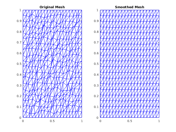
function d06ca_example


fprintf('d06ca example results\n\n');

imax = 20;
jmax = 20;
delta = 87;
nv = imax*jmax;

hx = 1/(imax-1);
hy = 1/(jmax-1);
rad = 0.01*delta*min(hx,hy)/2;

% Initialise the seed for the random number generator
seed = [int64(1762541)];
% genid and subid identify the base generator
genid = int64(1);
subid = int64(1);
% Initialise the generator to a repeatable sequence
[state, ifail] = g05kf(genid, subid, seed);

% Generate two sets of uniform random variates
[state, x1, ifail] = g05sq(int64(nv), 0, rad, state);
[state, x2, ifail] = g05sq(int64(nv), 0, 2*pi, state);

% Generate a simple uniform mesh and then distort it
% randomly within the distortion neighbourhood of each node.
coor = zeros(2, nv);
conn = zeros(3, 2*nv-1, 'int64');
k = 0;
ind = 0;
for j = 1:jmax
  for i = 1:imax
    k = k + 1;
    r = x1(k);
    theta = x2(k);

    if (i==1 || i==imax || j==1 || j==jmax)
      r = 0;
    end

    coor(1,k) = (i-1)*hx + r*cos(theta);
    coor(2,k) = (j-1)*hy + r*sin(theta);

    if (i<imax && j<jmax)
      ind = ind + 1;
      conn(1,ind) = k;
      conn(2,ind) = k + 1;
      conn(3,ind) = k + imax + 1;
      ind = ind + 1;
      conn(1,ind) = k;
      conn(2,ind) = k + imax + 1;
      conn(3,ind) = k + imax;
    end
  end
end

nelt = ind;

% Boundary edges
nedge = 0;
edge = zeros(3, 100, 'int64');
for i = 1:imax - 1
  nedge = nedge + 1;
  edge(1,nedge) = i;
  edge(2,nedge) = i + 1;
  edge(3,nedge) = 0;
end

for i = 1:jmax - 1
  nedge = nedge + 1;
  edge(1,nedge) = i*imax;
  edge(2,nedge) = (i+1)*imax;
  edge(3,nedge) = 0;
end

for i = 1:imax - 1
  nedge = nedge + 1;
  edge(1,nedge) = imax*jmax - i + 1;
  edge(2,nedge) = imax*jmax - i;
  edge(3,nedge) = 0;
end

for i = 1:jmax - 1
  nedge = nedge + 1;
  edge(1,nedge) = (jmax-i)*imax + 1;
  edge(2,nedge) = (jmax-i-1)*imax + 1;
  edge(3,nedge) = 0;
end

numfix = zeros(0, 0, 'int64');
itrace = int64(1);
nqint = int64(10);

% Plot original mesh
fig1 = figure;
subplot(1,2,1);
triplot(transpose(double(conn(:,1:nelt))), coor(1,:), coor(2,:));
title ('Original Mesh');

[coor, ifail] = d06ca(coor, edge(:, 1:nedge), conn(:, 1:nelt), ...
                      numfix, itrace, nqint);

fprintf('\nComplete smooth mesh characteristics:\n');
fprintf('  nv    = %d\n', nv);
fprintf('  nelt  = %d\n', nelt);

% Plot smoothed mesh
subplot(1,2,2);
triplot(transpose(double(conn(:,1:nelt))), coor(1,:), coor(2,:));
title ('Smoothed Mesh');


d06ca example results

 BEFORE SMOOTHING
 Minimum smoothness measure:       1.0060557
 Maximum smoothness measure:      45.7310387
 Distribution interval            Number of elements
      1.0060557 -       5.4785540       715
      5.4785540 -       9.9510523         4
      9.9510523 -      14.4235506         1
     14.4235506 -      18.8960489         0
     18.8960489 -      23.3685472         0
     23.3685472 -      27.8410455         0
     27.8410455 -      32.3135438         0
     32.3135438 -      36.7860421         0
     36.7860421 -      41.2585404         0
     41.2585404 -      45.7310387         1

 AFTER SMOOTHING
 Minimum smoothness measure:       1.3377832
 Maximum smoothness measure:       1.4445226
 Distribution interval            Number of elements
      1.3377832 -       1.3484572         0
      1.3484572 -       1.3591311        13
      1.3591311 -       1.3698050        42
      1.3698050 -       1.3804790       104
      1.3804790 -       1.3911529       162
      1.3911529 -       1.4018268       159
      1.4018268 -       1.4125008       122
      1.4125008 -       1.4231747        74
      1.4231747 -       1.4338486        31
      1.4338486 -       1.4445226        14

Complete smooth mesh characteristics:
  nv    = 400
  nelt  = 722
d06ca_fig1.png

PDF version (NAG web site, 64-bit version, 64-bit version)
Chapter Contents
Chapter Introduction
NAG Toolbox

© The Numerical Algorithms Group Ltd, Oxford, UK. 2009–2015