D06DBF joins together (restitches) two adjacent, or overlapping, meshes.
| SUBROUTINE D06DBF ( |
EPS, NV1, NELT1, NEDGE1, COOR1, EDGE1, CONN1, REFT1, NV2, NELT2, NEDGE2, COOR2, EDGE2, CONN2, REFT2, NV3, NELT3, NEDGE3, COOR3, EDGE3, CONN3, REFT3, ITRACE, IWORK, LIWORK, IFAIL) |
| INTEGER |
NV1, NELT1, NEDGE1, EDGE1(3,NEDGE1), CONN1(3,NELT1), REFT1(NELT1), NV2, NELT2, NEDGE2, EDGE2(3,NEDGE2), CONN2(3,NELT2), REFT2(NELT2), NV3, NELT3, NEDGE3, EDGE3(3,*), CONN3(3,*), REFT3(*), ITRACE, IWORK(LIWORK), LIWORK, IFAIL |
| REAL (KIND=nag_wp) |
EPS, COOR1(2,NV1), COOR2(2,NV2), COOR3(2,*) |
|
D06DBF joins together two adjacent, or overlapping, meshes. If the two meshes are adjacent then vertices belonging to the part of the boundary forming the common interface should coincide. If the two meshes overlap then vertices and triangles in the overlapping zone should coincide too.
This routine is partly derived from material in the MODULEF package from INRIA (Institut National de Recherche en Informatique et Automatique).
None.
- 1: EPS – REAL (KIND=nag_wp)Input
On entry: the relative precision of the restitching of the two input meshes (see
Section 8).
Suggested value:
.
Constraint:
.
- 2: NV1 – INTEGERInput
On entry: the total number of vertices in the first input mesh.
Constraint:
.
- 3: NELT1 – INTEGERInput
On entry: the number of triangular elements in the first input mesh.
Constraint:
.
- 4: NEDGE1 – INTEGERInput
On entry: the number of boundary edges in the first input mesh.
Constraint:
.
- 5: COOR1(,NV1) – REAL (KIND=nag_wp) arrayInput
On entry: contains the coordinate of the th vertex of the first input mesh, for ; while contains the corresponding coordinate.
- 6: EDGE1(,NEDGE1) – INTEGER arrayInput
On entry: the specification of the boundary edges of the first input mesh. and contain the vertex numbers of the two end points of the th boundary edge. is a user-supplied tag for the th boundary edge.
Constraint:
and , for and .
- 7: CONN1(,NELT1) – INTEGER arrayInput
On entry: the connectivity between triangles and vertices of the first input mesh. For each triangle
, gives the indices of its three vertices (in anticlockwise order), for and .
Constraints:
- ;
- ;
- and , for and .
- 8: REFT1(NELT1) – INTEGER arrayInput
On entry: contains the user-supplied tag of the th triangle from the first input mesh, for .
- 9: NV2 – INTEGERInput
On entry: the total number of vertices in the second input mesh.
Constraint:
.
- 10: NELT2 – INTEGERInput
On entry: the number of triangular elements in the second input mesh.
Constraint:
.
- 11: NEDGE2 – INTEGERInput
On entry: the number of boundary edges in the second input mesh.
Constraint:
.
- 12: COOR2(,NV2) – REAL (KIND=nag_wp) arrayInput
On entry: contains the coordinate of the th vertex of the second input mesh, for ; while contains the corresponding coordinate.
- 13: EDGE2(,NEDGE2) – INTEGER arrayInput
On entry: the specification of the boundary edges of the second input mesh. and contain the vertex numbers of the two end points of the th boundary edge. is a user-supplied tag for the th boundary edge.
Constraint:
and , for and .
- 14: CONN2(,NELT2) – INTEGER arrayInput
On entry: the connectivity between triangles and vertices of the second input mesh. For each triangle
, gives the indices of its three vertices (in anticlockwise order), for and .
Constraints:
- ;
- ;
- and , for and .
- 15: REFT2(NELT2) – INTEGER arrayInput
On entry: contains the user-supplied tag of the th triangle from the second input mesh, for .
- 16: NV3 – INTEGEROutput
On exit: the total number of vertices in the resulting mesh.
- 17: NELT3 – INTEGEROutput
On exit: the number of triangular elements in the resulting mesh.
- 18: NEDGE3 – INTEGEROutput
On exit: the number of boundary edges in the resulting mesh.
- 19: COOR3(,) – REAL (KIND=nag_wp) arrayOutput
-
Note: the second dimension of the array
COOR3
must be at least
.
On exit: will contain the coordinate of the th vertex of the resulting mesh, for ; while will contain the corresponding coordinate.
- 20: EDGE3(,) – INTEGER arrayOutput
-
Note: the second dimension of the array
EDGE3
must be at least
. This may be reduced to
once that value is known.
On exit: the specification of the boundary edges of the resulting mesh.
will contain the vertex number of the
th end point (
) of the
th boundary or interface edge.
If the two meshes overlap, will contain the same tag as the corresponding edge belonging to the first and/or the second input mesh.
If the two meshes are adjacent,
| (i) |
if the th edge is part of the partition interface, then will contain the value where and are the tags for the same edge of the first and the second mesh respectively; |
| (ii) |
otherwise, will contain the same tag as the corresponding edge belonging to the first and/or the second input mesh. |
- 21: CONN3(,) – INTEGER arrayOutput
-
Note: the second dimension of the array
CONN3
must be at least
. This may be reduced to
once that value is known.
On exit: the connectivity between triangles and vertices of the resulting mesh.
will give the indices of its three vertices (in anticlockwise order), for and .
- 22: REFT3() – INTEGER arrayOutput
-
Note: the dimension of the array
REFT3
must be at least
. This may be reduced to
once that value is known.
On exit: if the two meshes form a partition,
will contain the same tag as the corresponding triangle belonging to the first or the second input mesh, for . If the two meshes overlap, then
will contain the value where and are the user-supplied tags for the same triangle of the first and the second mesh respectively, for .
- 23: ITRACE – INTEGERInput
On entry: the level of trace information required from D06DBF.
- No output is generated.
- Details about the common vertices, edges and triangles to both meshes are printed on the current advisory message unit (see X04ABF).
- 24: IWORK(LIWORK) – INTEGER arrayWorkspace
- 25: LIWORK – INTEGERInput
On entry: the dimension of the array
IWORK as declared in the (sub)program from which D06DBF is called.
Constraint:
.
- 26: IFAIL – INTEGERInput/Output
-
On entry:
IFAIL must be set to
,
. If you are unfamiliar with this parameter you should refer to
Section 3.3 in the Essential Introduction for details.
For environments where it might be inappropriate to halt program execution when an error is detected, the value
is recommended. If the output of error messages is undesirable, then the value
is recommended. Otherwise, if you are not familiar with this parameter, the recommended value is
.
When the value is used it is essential to test the value of IFAIL on exit.
On exit:
unless the routine detects an error or a warning has been flagged (see
Section 6).
If on entry
or
, explanatory error messages are output on the current error message unit (as defined by
X04AAF).
Not applicable.
D06DBF finds all the common vertices between the two input meshes using the relative precision of the restitching parameter
EPS. You are advised to vary the value of
EPS in the neighbourhood of
with
to get the optimal value for the meshes under consideration.
For this routine two examples are presented. There is a single example program for D06DBF, with a main program and the code to solve the two example problems given in Example 1 (EX1) and Example 2 (EX2).
This example involves the unit square
meshed uniformly, and then translated by a vector
(using
D06DAF). This translated mesh is then restitched with the original mesh. Two cases are considered:
| (a) |
overlapping meshes (, ), |
| (b) |
partitioned meshes (, ). |
The mesh on the unit square has
vertices,
triangles and its boundary has
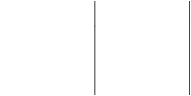
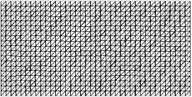
edges. In the overlapping case the resulting geometry is shown in
Figure 1 and
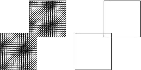
Figure 2. The resulting geometry for the partitioned meshes is shown in
Figure 3.
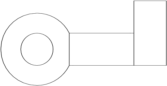
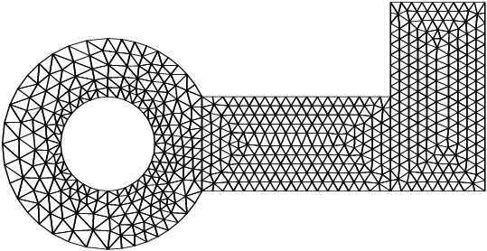
This example restitches three geometries by calling the routine D06DBF twice. The result is a mesh with three partitions. The first geometry is meshed by the Delaunay–Voronoi process (using
D06ABF), the second one meshed by an Advancing Front algorithm (using
D06ACF), while the third one is the result of a rotation (by
) of the second one (using
D06DAF). The resulting geometry is shown in
Figure 4 and
Figure 5.
Figure 1: The boundary and the interior interfaces of the two partitioned squares geometry
Figure 2: The interior mesh of the two partitioned squares geometry
Figure 3: The boundary and the interior interfaces (left); the interior mesh (right)
of the two overlapping squares geometry
Figure 4: The boundary and the interior interfaces of the double restitched geometry
Figure 5: The interior mesh of the double restitched geometry